
The sewage source heat pump system utilizes wastewater, in conjunction with a refrigeration cycle, to extract low-grade energy from wastewater resources during winter for heating purposes by consuming a small amount of electricity. In summer, it removes heat from indoor spaces and releases it into the wastewater to achieve cooling effects.
Advantages of Sewage Source Heat Pump Unit
Innovative Technologies
Designed in full compliance with national standards and tailored for industrial waste heat conditions, enabling direct utilization of medium- and low-grade heat energy within the 10–60°C range. This fundamentally addresses the current limitations in recycling such waste heat resources.
Large temperature difference design: The supply-return water temperature difference is configured at 20°C, meeting the external network requirements for radiator-based heating systems.
Specialized high-temperature eco-friendly refrigerant ensures safe and reliable operation in high-temperature zones.
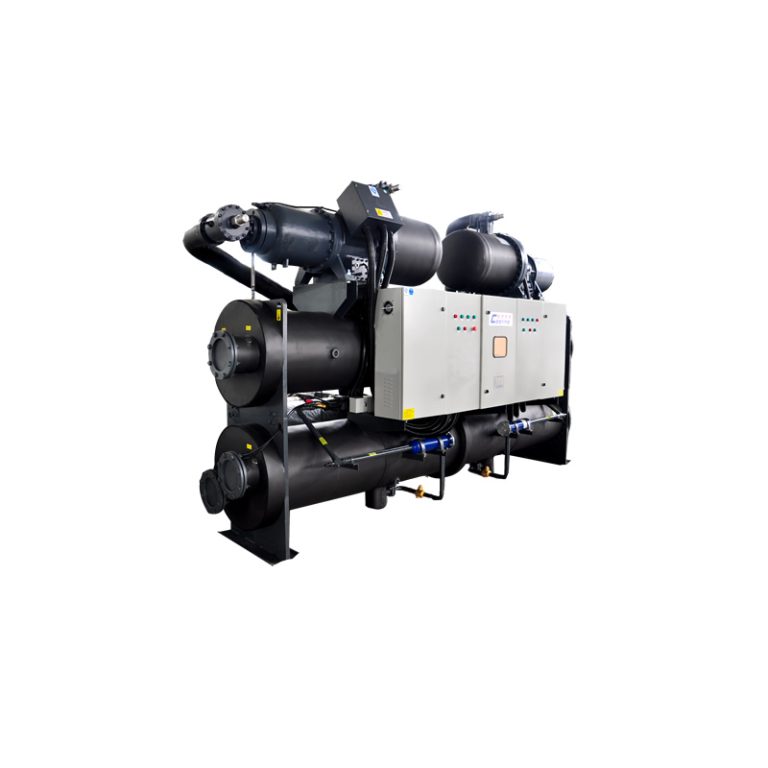
Premium Components
Brand-name specialized compressors, refrigeration, and electrical control components ensure highly efficient and reliable unit operation.
Electronic expansion valves enable precise throttling adjustment, rapid response to load changes, and high part-load performance coefficients.
Patented high-efficiency heat exchangers, made of corrosion-resistant materials, are suitable for various types of industrial wastewater, offering high heat transfer efficiency and long service life.
User-Friendly Operation
Full-color touchscreen with Chinese interface for intuitive human-machine interaction.
Fully automated microcomputer control enables unattended operation.
Comprehensive dedicated control programs and multiple protection functions ensure safer and more reliable unit performance.
Remote Control Capabilities
Remote control, data collection, and printing via computer networks.
Compatible with main control room systems for centralized management.
Pre-equipped expansion and upgrade ports for future enhancements.
Waste-to-Energy Conversion
Recovers substantial amounts of medium- and low-grade heat energy from industrial cooling water and wastewater, converting it into directly usable high-grade heat energy, thereby saving significant primary energy resources.
Environmentally Friendly
Replaces boiler systems, eliminating combustion processes and associated pollutants such as flue gas and dust.
Eliminates the need for cooling towers, avoiding noise, mold, and thermal pollution, contributing to a cleaner environment.
Economical and Practical
Input of 1 kW of electricity yields over 4 kW of high-grade heat energy.
Initial comprehensive investment is slightly higher than that of boiler plants, but operating costs are only 1/12 to 2/13 of traditional methods, with a typical payback period of 1–2 years.
Applications:Widely applicable in industries such as power plants, grain processing, oilfields, petrochemicals, metallurgy, coal, aquaculture, textiles, food processing, and geothermal tailwater. Recovered heat can be used for heating system retrofits, domestic hot water, and industrial process hot water preparation.